1. Database Definition
The database (English language: a database), or often also spelled database, is the collection of information stored in the computer so that it can be systematically examined using a computer program to obtain information from the data base. Software used to manage and call the query (query) of data base is called the database management system (DBMS).
Basic concept of the database is a collection of records, or snippets of knowledge. A database has a structured explanation of the types of facts stored in it: this description is called the scheme. Scheme describes the objects that represented a data base, and the relationship between these objects. There are many ways to organize the scheme, or structure model of the database: this is known as the database model or data model. Model that is now commonly used relational model, according to Layman: the term represents all the information in the form of table-related tables where each table consists of rows and columns (using the definition of the actual mathematical terminology). In this model, the relationship between the table represented by using the same value across the table. The other models, such as the hierarkis network model and use a more explicit way to represent relationships between tables.
2. Database Management System
A Database Management System (DBMS) is an organised set of facilities for accessing and maintaining one or more databases. A DBMS is a shell which surrounds a database or series of databases and through which all interactions take place with the database. The interactions catered for by most existing DBMS fall into four main groups:
a. Data definition – defining new data structures for a database, removing data structures from the database, modifying the structure of existing data.
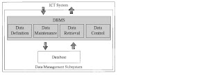
b. Data maintenance – inserting new data into existing data structures, updating data in existing data structures, deleting data from existing data structures.
c. Data retrieval – querying existing data by end-users and extracting data for use by application programs.
d. Data control – creating and monitoring users of the database, restricting access to data in the database and monitoring the performance of databases.
3. Data Definition
A database is effectively a set of data structures for organising and storing data. In any data model, and consequently in any DBMS, we must have a set of principles for exploiting such data structures for information systems applications within organisations. Data definition is the process of exploiting the inherent data structures of a data model for a particular organisational application.
3.1 Relations
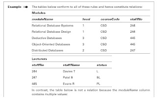
There is only one data structure in the relational data model – the relation. Because the idea of a relation is modelled on a mathematical construct, a relation is a table which obeys a certain restricted set of rules:
- Every relation in a database must have a distinct name.
- Every column in a relation must have a distinct name within the relation.
- All entries in a column must be of the same kind. They are said to be defined on the same domain.
- The ordering of columns in a relation is not significant.
- Each row in a relation must be distinct. In other words, duplicate rows are not allowed in a relation.
- The ordering of rows is not significant.
- Each cell or column/row intersection in a relation should contain only a socalled atomic value. In other words, multiple-values are not allowed in the cells of a relation
3.2 Primary Key
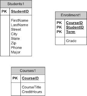
Each relation must have a primary key. This is to enforce the property that duplicate rows are forbidden in a relation. A primary key is one or more columns of a table whose values are used to uniquely identify each of the rows in a table. In any relation there may be a number of candidate keys; that is, a column or group of columns which can act in the capacity of a unique identifier. The primary key is chosen from one of the candidate keys.
Example:
Consider the relation named Lecturers above. The attributes staffNo, staffName and status are currently candidate keys since the values in these columns are currently unique. We know in practice, of course, that as the size of the lecturers table grows, we may store information about more than one lecturer named Evans R, and more than one lecturer is likely to be a senior lecturer – an SL. This leaves staffNo – a unique code for each lecturer of a university – as the only practicable primary key.
Any candidate key, and consequently any primary key, must have two properties. It must be unique, and it must not be null – a special character being used to indicate a missing or incomplete datum. First, by definition any candidate key must be a unique identifier. Hence, there can be no duplicate values in a candidate or primary key column. Second, we must have a primary key value for each row in a table. In other words, we cannot have a null (non-existent)
value within a primary key column or columns. Picture below is example of primary key.
3.3 Domains
The primary unit of data in the relational data model is the data-item. Such data-items are said to be non-decomposable or atomic. A set of such data-items of the same type is said to be a domain. Domains are therefore pools of values from which actual values appearing in the columns of a table are drawn.
Example:
Examples of data-items include a staff number such as 244, a lecturer name such as S Patel or a student’s date of birth such as 1/7/1986. Suppose there are four members of staff in our institution with the staff numbers 244, 386, 534 and 222. The domain of staff numbers is the set of all possible staff numbers, in our case {244, 386, 534, 222}.
3.4 Foreign Key
Foreign keys are the means of interconnecting the data stored in a series of disparate tables. A foreign key is a column or group of columns of some table which draws its values from the same domain as the primary key of some related table in the database.
Example:
Consider the relation named Lecturers above. staffNo is a foreign key in the modules table. This column draws its values from the same domain as the staffNo column – the primary key of the lecturers table. This means that when we know the staffNo of some lecturer we can cross-refer to the lecturers table to see, for instance, the status of that lecturer.
3.5 Super Key
Superkey is one or more attributes of a table that can be used to identify the entity / record from the table which are unique (not all attributes can be superkey).
3.6 Candidate Key
Candidate Key is a super key with minimal attributes. Candidate must not contain a key attribute of the table so that the other candidate key is certain superkey but not necessarily vice versa.
4. Entity Relationship Model
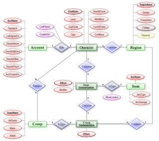
Entity-Relationship Model (ERM) is an abstract and conceptual representation of data. Entity-relationship modeling is a database modeling method, used to produce a type of conceptual schema or semantic data model of a system, often a relational database, and its requirements in a top-down fashion.
Diagrams created using this process are called entity-relationship diagrams, or ER diagrams or ERDs for short. The definitive reference for entity relationship modelling is generally given as Peter Chen's 1976 paper[1]. However, variants of the idea existed previously (see for example A.P.G. Brown[2]) and have been devised subsequently.

5. Data Models
5.1 Entities
An entity may be defined as a thing which an organisation recognises as being capable of an independent existence and which can be uniquely identified. An entity is an abstraction from the complexities of some domain. When we speak of an entity we normally speak of some aspect of the real world which can be distinguished from other aspects of the real world. An entity may be a physical object such as a house or a car, an event such as a house sale or a car service, or a concept such as a customer transaction or order. Although the term entity is the one most commonly used, following Chen (1976) we should really distinguish between an entity and an entitytype.
An entity-type is a category. An entity, strictly speaking, is an instance of a given entity-type. There are usually many instances of an entity-type. It must be remembered however that whenever we refer to an entity we normally mean an entity-type. Entities are by their very nature interesting things because entities are normally used to define logical data groupings. In conventional information systems jargon the term logical data grouping normally means a file. One rule of thumb to apply in identifying suitable entities for a given application is therefore the following:
If you need to store data about many properties of some thing, then that thing is likely to be an entity.
5.2 Relationship
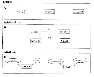
A relationship is some association between entities. In this section we shall concentrate on binary relationships. That is, associations between two entities. In section 16.4 we shall introduce other N-ary relationships. That is, relationships between one, three, four or N entities. In the E–R approach, more than one relationship can exist between any two entities.
5.3 Attributes
As a real-world aspect, an entity is characterised by a number of properties or attributes. Values assigned to attributes are used to distinguish one entity from another. We also choose one or more attributes to act as identifiers for instances of an entity.
This picture below is the examples of entities, relationship, and attributes.
6. Cardinality
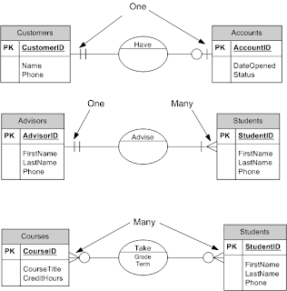
Cardinality (or degree) concerns the number of instances involved in a relationship. A relationship can be said to be either a 1:1 (one-to-one) relationship, a 1:M (one-to-many) relationship, or a M:N (many-to-many) relationship.
Example:
The relationship between a Bankaccount entity and a Customer entity can be said to be one-to-one (1:1) if it can be defined in the following way:
A bank account is held by at most one customer
A customer may hold at most, one bank account
In contrast, the relationship between Bankaccount and Customer is one-to-many (1:M) if it is defined as:A customer may hold at most, one bank account
A customer holds many bank accounts
A bank account is held by at most one customer
Finally, we are approaching a realistic representation of the relationship when we describe it as being many-to-many (M:N). That is:A bank account is held by at most one customer
A customer holds many bank accounts
A bank account may be held by many customers
A bank account may be held by many customers

The other example of Cardinality:
7. E-R Notation

0 comments:
Post a Comment